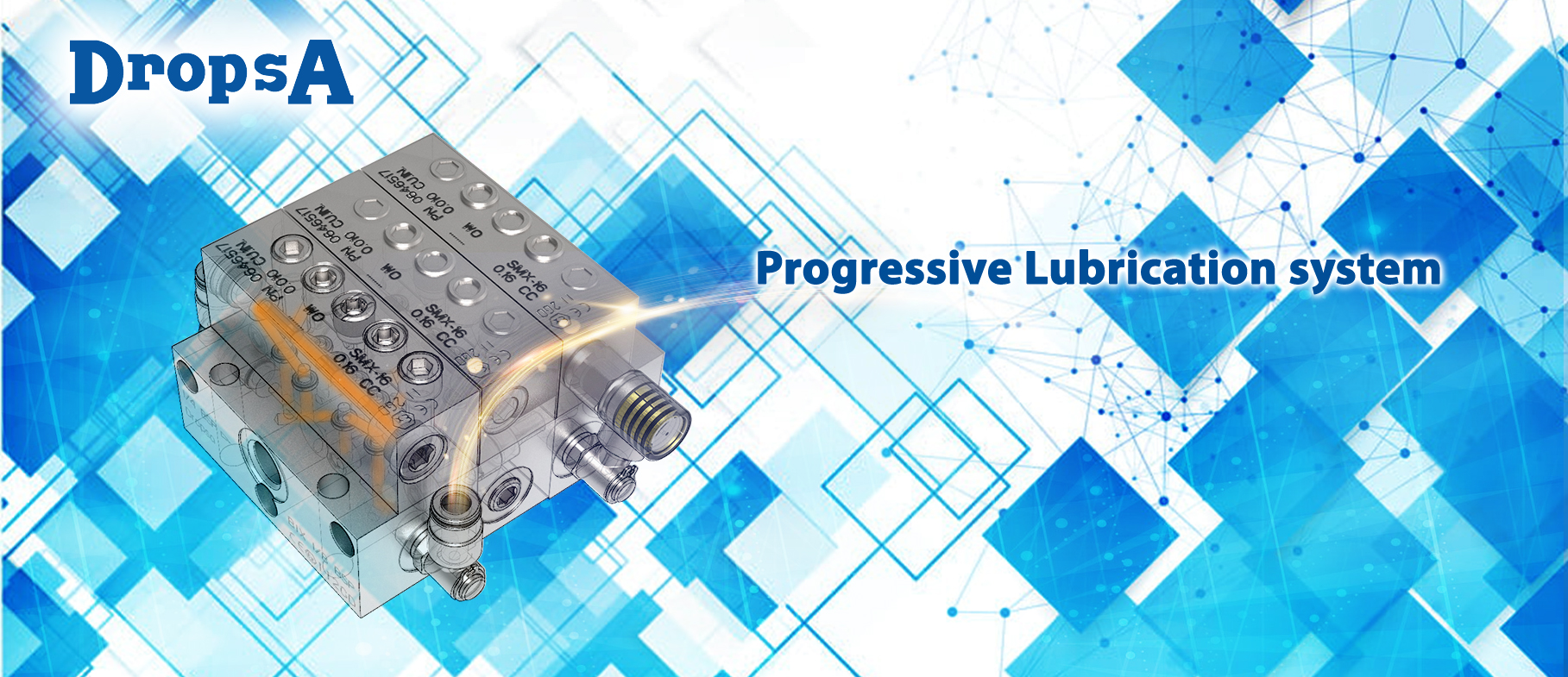
After the overall definition of the various types of lubrication systems and their benefits was presented, a specific solution can be focused on: the progressive system – line 26.
The progressive system is simple to monitor and control, can be fed with a manual, electric, or pneumatic pump, and is engineered to utilize a combination of a base and modular dividers.
These lubrication devices constitute the progressive lubrication system, which is effective with both Grease and Oil, allowing this system to be utilized in a grease system or oil solution.
A Progressive system distributes the lubricant flow of a pump into separate “progressive outlets” by the use of a progressive spool arrangement. The modular concept allows for the quick replacement of a blocked or damaged element.
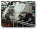
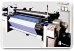
This solution is suitable for small, medium, and large machines with multiple points that require complete control of machine lubrication operations (machine tools, wood working machines, presses, and textiles machines).
A progressive system - line 26 is suitable for use in the following situations:
- Small to medium sized total loss oil or grease lubrication systems (also recirculating/low flow rate)
- Applications with multiple points (usually less than 300 points)
- Require easy and economical monitoring, through a cycle sensor “Ultrasensor”
- Pneumatic, electric, or manual systems (feasible, however, not recommended)
- Need for the “zoning” of a manufacturing facility (multiple machines or machine parts that require a variation of output of lubrication)
- Ability to work in ATEX zones and in marine environments (INOX 316)
In a progressive system, the lubricant is supplied to a single inlet of a “progressive divider” or “divider” and is distributed volumetrically through an engineered number of outlets due to the progressive movement of the pistons arranged in a sequence.
Since the divider valves are in series with each other, each piston can dispense lubricant only when the previous piston has completed its delivery. Therefore, a blocked output will cause failure of operation of all progressive dividers connected to each other.
Furthermore, it is only necessary to monitor a single element to effectively detect a fault or blockage of lines.
THE OPERATING PRINCIPLE
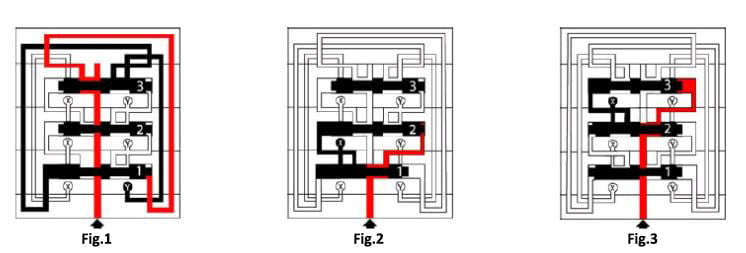
Fig.1: The lubricant passes along all of the elements and progressively flows, under pressure, towards the right of all the divider’s pistons.
Fig.2: Then the flow actuates the right side of the first piston.
Fig.3: The first piston shifts to the left and then reverses the direction of flow, so that all the other pistons will be brought in the same position.
Continuing, the lubricant flow will shift the first piston to the right, bringing the system back to the initial configuration of Figure 1.
The metered output in outlets “X” and “Y” is controlled by the amount of lubricant accumulated from the previous operating phase.
It’s necessary to know that each piston represents a segment or “element”, and that a divider must be composed of a minimum of three working elements.
A progressive divider is a continuous system and will dispense lubricant until no inlet pressure remains. A cycle sensor has the ability to stop the pump when a predetermined amount of lubricant needed has been reached.
- A maximum total of three levels of progressive blockscan be effectively used in a lubrication solution. (Master, secondary, tertiary)
- If a segment or element is blocked, the entire system is effectively gridlocked, therefore, it is sufficient to monitor a single element or segment to oversee an entire lubrication solution.
- It is necessary to have a minimum pressure of 20/25 bar at the divider block inlet. Additionally, it is important to consider the pressure drops deriving from the length of the tube being used to feed the system.